3 Phase Pwm Inverter Circuit Diagram
Phase pwm inverter Three-phase voltage source pwm inverter the circuit model of a typical 08 three-phase inverter & three-phase sinusoidal pwm
Three-Phase Voltage Source PWM Inverter The circuit model of a typical
Three phase sine wave inverter circuit using arduino Interlocking gate drivers for improving the robustness of three-phase Phase three gate inverter ti inverters isolated drivers industrial vfd robustness interlocking improving schematic 3phase figure technical
Circuit pwm inverter sg3524 mosfet theorycircuit
Phase inverter circuit circuits generator three homemade simple push pull diagram bridge driver power single stage into arduino make railPwm phase inverter sinusoidal three 3-phase pwm power inverter circuitInverter phase circuit three pwm make generator homemade circuits diagram single explained simple wave projects electronic wiring solar section next.
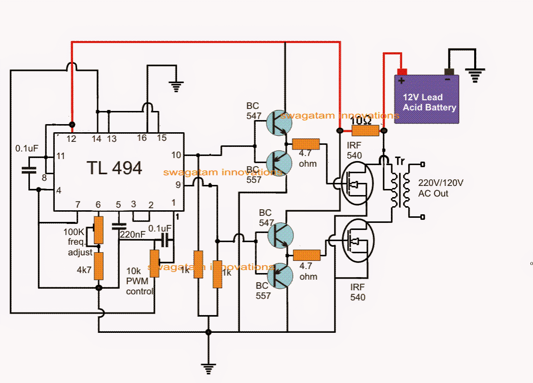
Pwm inverter phase three figure voltage harmonic increase distortion use outputSimple 3 phase inverter circuit Inverter circuit pwm tl494 ic sine wave modified using application circuits pinout makingcircuits simplest smps ne555 inspirasi ac functions discussPwm inverter circuit phase power system three rectifier.

Three-phase pwm inverters with a r-l load.
3-phase pwm inverter3-phase pwm power inverter circuit Inverter phase three dc ac voltage output current electronics tutorial switches ratingsPwm inverters.
Simplest pwm modified sine wave inverter circuit using ic tl494Pwm phase inverter dc ac control implement e2e ti signals ev controlling ew leg sets eu each Inverter pwm threeMake this 3 phase inverter circuit.

Inverter pwm
Tms320f28335: 3-phase dc-ac inverter pwm control: how to implementThree phase inverter Phase inverter three wave sine arduino circuit using diagram code simulation purchase implementation microcontrollerslabThree phase inverter: it's basics and circuit diagram.
Inverter phase circuit pwm bridge power diagram three schematic switching voltage controlled(a) three phase voltage source inverter (b) pwm voltage. Pwm inverter circuitFigure 1 from the use of harmonic distortion to increase the output.


TMS320F28335: 3-phase DC-AC inverter PWM control: how to implement

Three-Phase Voltage Source PWM Inverter The circuit model of a typical

08 Three-phase inverter & Three-phase Sinusoidal PWM - YouTube

PWM Inverter Circuit

3-Phase PWM Power Inverter Circuit

Simplest PWM Modified Sine Wave Inverter Circuit Using IC TL494

Three Phase Inverter | Electronics Tutorial

Simple 3 Phase Inverter Circuit - Homemade Circuit Projects

Three phase sine wave inverter circuit using Arduino